Honda’s Dual Clutch Transmission (DCT) is designed to provide smooth, comfortable and consistent gear changes by electronically controlling two separate clutches. Over time, however, the clutch engagement and shifting behaviour may change.
A DCT calibration, also referred to as clutch initialization, allows the system to relearn the clutch engagement characteristics and can help restore smooth shifting and clutch operation.
The procedure described on this page is intended as a practical reference for Honda DCT riders. Although the basic calibration procedure is similar across many Honda DCT models, the exact procedure and indications can vary depending on the model, DCT generation and model year.
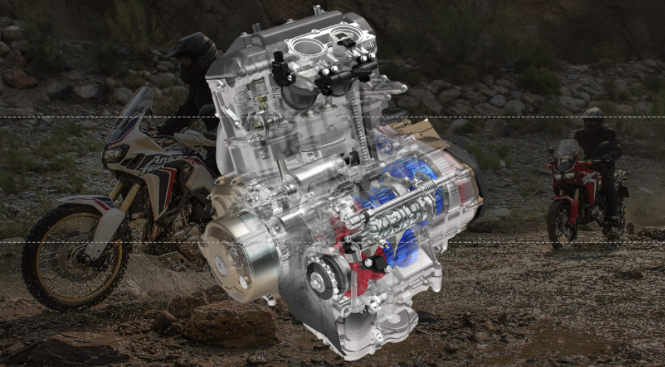
Honda’s DCT, the world’s first DCT mounted on a motorcycle, has evolved to be closer to the rider’s senses
In 2010, Honda introduced the world’s first dual clutch transmission (DCT)*1 in a motorcycle, and has continued to evolve the DCT ever since. 2012 saw the introduction of the DCT in the NC700 series and the CTX700, expanding the circle of users. In 2016, this technology was introduced to the CRF1000L Africa Twin to expand riders’ field of use. And in 2020, it evolved to become quieter and smoother, with control closer to the rider’s senses.
What is the Dual Clutch Transmission?
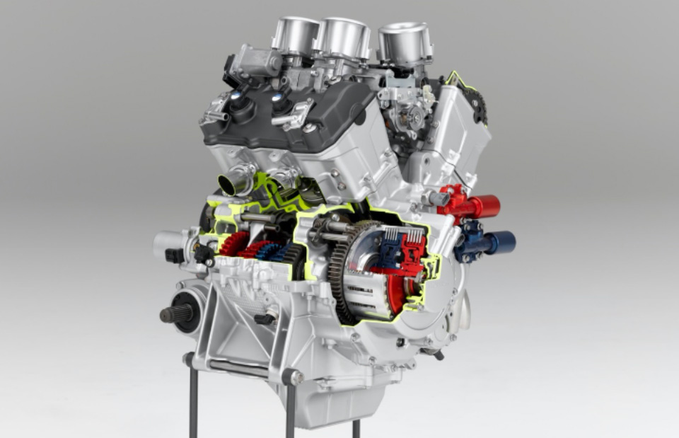
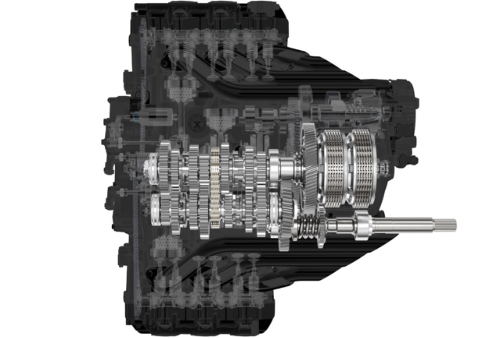
A Dual Clutch Transmission is a transmission in which clutch and shift operations are automated, while maintaining the structure of manual transmission with its advantages such as direct-feel acceleration. With no need to operate the clutch, the rider can concentrate on the throttle and brake operation while riding, and smooth acceleration and deceleration is possible with fewer interruptions of driving force during shifting that inevitably occur with normal manual transmissions due to their structure. As a transmission with two clutches (dual clutch), one for the 1st, 3rd, 5th gear and starting, and the other for the 2nd, 4th, and 6th gear, Dual Clutch Transmission is the world’s first*1 technology for motorcycles.
*1: As of June 2010 (based on Honda research)
There are two gear shifting modes: the AT mode, which automates shifting operation, and the MT mode, which allows the rider to select a gear of their choice at any time. In the AT mode, in addition to the regular D mode, the S mode can be selected for sportier riding. The gears can be shifted at any time with shift switching according to the riding conditions, and after shifting the gears, the machine automatically returns to the AT mode.
The CRF1100L Africa Twin is equipped with a 6-axis IMU (inertial sensor) that detects angular velocity and acceleration for pitch, roll, and yaw. The addition of cornering run detection control enables gear shifting closer to the rider’s senses, while enhancing launch control and gearshift control delivers a sense of security and directness.
The Inner Workings of the Dual Clutch Transmission
We would like to present here the clutch operation and gear shift operation performed automatically during acceleration and deceleration.
Mechanism for Automatic Gear Switching
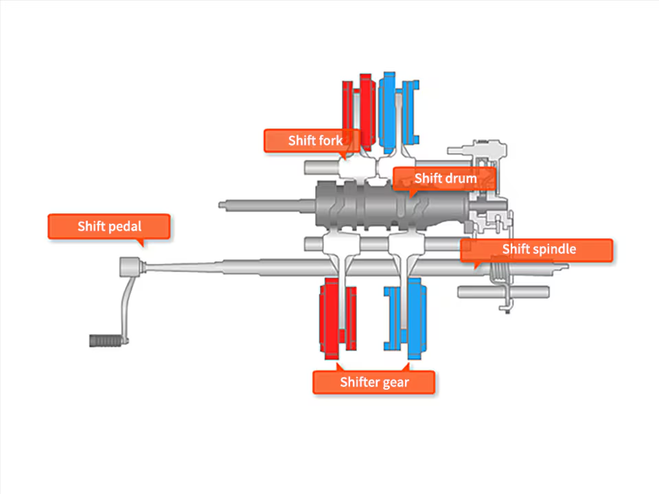
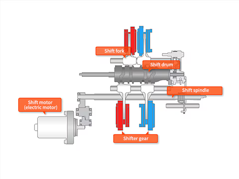
In a normal manual transmission, the shift spindle is rotated by operating the shift pedal on the left foot, and the gears are slid through the shift drum and shift fork, but in a dual clutch transmission, the shift motor takes on this role. The shift spindle is operated by the shift motor in the same way when using the optional foot pedal setting.
Shifting is possible by foot as well as by hand.
Dual Clutch Transmission Change Pedal Kit
Shift operation is possible by left foot just like a normal manual transmission vehicle. It can be used with the DCT shift switch on the handlebar.
Dual Clutch Transmission Shift Pedal
Efforts to Deliver to a Wider Audience
In order to deliver to as many people as possible the riding sensation of manual transmission that can be enjoyed without clutch and shift operations, we have optimized the structure according to the characteristics of the engine and model. For example, in the series where the same engine is mounted on the same frame in the three types, “NC750S”, “NC750X” and “X-ADV”, the layout of the clutch and crankshaft was reviewed to realize the floor-type step of the “X-ADV”.
Dual Clutch Transmission-Installed Models
Gold Wing (DCT)Gold Wing Tour (DCT)CRF1100L Africa Twin (DCT)CRF1100L Africa Twin Adventure Sports (DCT)NT 1100 (DCT)Forza 750 (DCT) NC750X (DCT) X-ADV (DCT) Rebel 1100 (DCT)
Developers’ thoughts
We believe that the ultimate goal of the DCT is to “create the pleasure of maneuvering”. Since the creation of the DCT in 2010, the development team members have continued to work on evolving it to realize the purpose.
The DCT is an excellent system that frees the rider from clutch and shift operations, while still being able to transmit “direct drive power” unlike other ATs; it does not spoil the fun riding that is the essence of motorcycles.
If you actually ride it, you will immediately understand that it is not just a regular AT. It allows the rider to get the torque and acceleration they want, when they want it, and how they want it. What we want to provide with the DCT is a sense of oneness between the rider and the motorcycle.
2010: “Establishment of the world’s first installation system”
After announcing the development of our technology at the Milan Show 2008, in 2010, the VFR1200F sports tourer became the first motorcycle in the world to be equipped with Dual Clutch Transmission. It is since this time that the idea of switching between AT and MT modes at the will of the rider, and temporarily allowing manual operation even when the AT mode is used has been adopted.
Mounted on the VFR1200F in 2010/VFR1200X in 2014
2012: “Expansion of Users”
In 2012, the Dual Clutch Transmission was introduced to the 700cc NC series to allow more riders to experience it. By utilizing the know-how and manufacturing infrastructure of four-wheelers, to which hydraulic clutch control was applied ahead of motorcycles, we have been able to offer a more compact and reasonable model by drastically reviewing the structure, including reducing the number of parts compared to the previous systems. As the NC series gained popularity, many derivative models were equipped with DCT, and as more and more riders experienced it, it has grown its way to being a widely recognized technology.
Mounted on the NC700 series in 2012, CTX700 series in 2013, NM4 in 2014, NC750 series in 2016 and X-ADV in 2017
2016: “Expansion of the Field of Use”
With the Dual Clutch Transmission, we sought to expand not only the “users” but also the “field of use”-In the 2016 CRF1000L Africa Twin, we took on the challenge of applying the DCT to a new territory: off-roading. By reviewing the clutch control and gear shifting control, a new mode for dirt riding has been added, which has been well received as an “adventure model” as it can be ridden anywhere. For the Africa Twin, the DCT model was selected by almost half of the customers, proving that the DCT is capable of demonstrating its true value even in off-road conditions where riding requires concentration.
Mounted on the CRF1000L Africa Twin in 2016
2018: “7 gears for freedom of choice in shifting”
As the next step in our efforts to “expand” the range of users and scenes, we aimed to “deepen” the sense of fulfillment of maneuvering the vehicle by ensuring that the evolution of each model is optimized in terms of both software and hardware.
In the Gold Wing, the shifting feel has been improved by adopting a 7-gear transmission instead of 5-gear manual transmission, allowing the rider to enjoy the full power feel of the vehicle. With the adoption of a cross ratio on the low-speed side, the shock caused by shifting gears is reduced while the adoption of a wide ratio in 7th gear enables controlling of the engine speed rotation during high-speed cruising, greatly improving quietness. Furthermore, a superior shift feel has been achieved by adopting dampers in various parts to reduce transmission noise and operation noise while shifting. The adoption of a geared chain eliminates the need for an additional reversing shaft, which contributes to making the system lightweight and compact, coming along with a very low-speed forward and reverse function that allows for easy turning of the vehicle body while seated. In terms of advances in control technology, we have achieved both quicker and smooth-feel shifting through coordinated control with throttle-by-wire (TBW), which electronically controls the throttle valve opening.
Mounted on the Gold Wing Tour in 2018 and Gold Wing in 2019
2020: DCT Control that Paved its Way to be Closer to “the Rider’s Senses”
The CRF1100L Africa Twin uses a 6-axis IMU to detect the vehicle’s bank angle, acceleration, and deceleration, and to select gears that match the riding conditions, such as cornering. This enables gear shifting closer to the rider’s senses. Together with the G-Switch, which switches the clutch response characteristics, the rider can enjoy a direct and exciting ride.
The DCT technology is highly compatible with other technologies, and will continue to evolve as sensing devices, ECUs, AI, etc., are enhanced. We will continue to promote technological development with the aim of “creating a higher level pleasure of maneuvering”.
Mounted on the CRF1100L Africa Twin and CRF1100L Africa Twin Adventure Sports in 2020
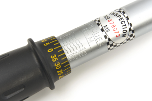
The torque values below provide the specified tightening torques for the engine, frame, chassis, braking system and other components. They are intended as a quick reference during maintenance and repair work. All values are given in N·m, with the corresponding kgf·m and lbf·ft values where specified. Always follow the applicable remarks, such as the use of thread-locking agent, engine oil or replacement of self-locking fasteners.
Engine & Frame Torque Values
Engine & Frame Torque Values
Torque tables transcribed from the supplied workshop manual PDF.
Torque is shown as N·m (kgf·m, lbf·ft).
FRAME BODY PANELS/EXHAUST SYSTEM
Item
Qty
Thread Dia. (mm)
Torque N·m (kgf·m, lbf·ft)
Remarks
Windscreen socket bolt
4
5
0.54 (0.06, 0.4)
Windscreen stay socket bolt
4
6
12 (1.2, 9)
Middle cowl socket bolt A
2
5
0.54 (0.06, 0.4)
Front side reflector nut
2
6
1.8 (0.2, 1.3)
Left rear cover bolt
2
6
12 (1.2, 9)
Clutch EOP sensor cover socket bolt
2
6
10 (1.0, 7)
Right rear engine cover socket bolt
2
6
10 (1.0, 7)
Left main step bracket bolt
2
10
35 (3.6, 26)
Sidestand switch bolt
1
6
10 (1.0, 7)
Replace with a new one.
Right main step bracket upper bolt
1
12
69 (7.0, 51)
Right main step bracket lower bolt
1
8
32 (3.3, 24)
Pillion step bracket bolt
4
8
32 (3.3, 24)
Upper deflector socket bolt (long)
2
5
0.54 (0.06, 0.4)
Upper deflector socket bolt (short)
4
5
0.42 (0.04, 0.3)
Right lower deflector socket bolt
3
5
0.54 (0.06, 0.4)
Left lower deflector socket bolt
3
5
0.54 (0.06, 0.4)
Rear center cowl socket bolt
2
5
0.42 (0.04, 0.3)
Rear carrier bolt
6
8
35 (3.6, 26)
Rear reflector nut
1
5
1.8 (0.18, 1.3)
Seat rail socket bolt
4
10
44 (4.5, 32)
Rear master cylinder reservoir mounting bolt
1
6
10 (1.0, 7)
Catalyst cover socket bolt
4
6
9.0 (0.92, 6.6)
Exhaust outer cover socket bolt
1
6
9.0 (0.92, 6.6)
Exhaust pipe cover C socket bolt
4
6
9.0 (0.92, 6.6)
Muffler band bolt
2
8
17 (1.7, 13)
Muffler cover screw
1
6
9.0 (0.92, 6.6)
Tail cap cover bolt
2
6
9.0 (0.92, 6.6)
Exhaust pipe cover band screw
2
–
2.8 (0.29, 2.1)
Worm screw
Exhaust pipe joint nut
4
8
20 (2.0, 15)
Exhaust pipe stud bolt
4
8
–
Sidestand pivot bolt
1
10
10 (1.0, 7)
Sidestand pivot nut
1
10
42 (4.3, 31)
Self lock nut
MAINTENANCE
Item
Qty
Thread Dia. (mm)
Torque N·m (kgf·m, lbf·ft)
Remarks
Air cleaner element mounting screw
4
5
1.1 (0.11, 0.8)
Tapping screw
Air cleaner cover screw
6
5
1.1 (0.11, 0.8)
Tapping screw
Spark plug
4
10
22 (2.2, 16)
Valve adjusting screw lock nut
4
5
10 (1.0, 7)
Apply engine oil to the threads and seating surface.
Timing hole cap
1
14
6.0 (0.61, 4.4)
Apply grease to the threads.
Crankshaft hole cap
1
30
8.0 (0.82, 5.9)
Apply grease to the threads.
Engine oil drain bolt
2
12
30 (3.1, 22)
Oil filter boss (crankcase side)
1
20
– Apply locking agent
to the threads.
Engine oil filter cartridge
1
20
26 (2.7, 19)
Apply engine oil to the threads.
Clutch oil filter cover bolt (DCT model)
2
6
12 (1.2, 9)
Rear axle nut
1
18
100 (10.2, 74)
Self-lock nut
Drive chain adjuster lock nut
2
8
27 (2.8, 20)
UBS-nut
Drive sprocket bolt
1
10
54 (5.5, 40)
Driven sprocket nut
6
10
64 (6.5, 47)
Self-lock nut
Oil bolt
5
10
34 (3.5, 25)
Brake pipe joint nut
4
10
14 (1.4, 10)
Apply brake fluid to the threads.
Parking brake adjuster lock nut (DCT model)
1
8
17.2 (1.8, 13)
PGM-FI SYSTEM
Item
Qty
Thread Dia. (mm)
Torque N·m (kgf·m, lbf·ft)
Remarks
A/F sensor
2
12
24.5 (2.5, 18)
MAP sensor screw/washer
1
6
4.9 (0.50, 3.6)
IAT sensor mounting screw
2
5
1.1 (0.11, 0.8)
ECT sensor
1
10
12 (1.2, 9)
GP sensor mounting bolt (MT model)
1
6
12 (1.2, 9)
Shift spindle switch
1
10
12 (1.2, 9)
Apply engine oil to the threads and seating surface.
Shift spindle switch terminal nut
1
4
1.7 (0.17, 1.3)
CKP sensor bolt
1
6
12 (1.2, 9)
ELECTRIC STARTER
Item
Qty
Thread Dia. (mm)
Torque N·m (kgf·m, lbf·ft)
Remarks
Starter motor cable terminal nut/washer
1
6
10 (1.0, 7)
Starter motor setting bolt
2
5
4.9 (0.50, 3.6)
Negative brush screw/washer
1
5
3.7 (0.38, 2.7)
FUEL SYSTEM
Item
Qty
Thread Dia. (mm)
Torque N·m (kgf·m, lbf·ft)
Remarks
Fuel filler cap bolt
3
4
1.8 (0.18, 1.3)
Front cross plate bolt
4
6
12 (1.2, 9)
Fuel pump unit mounting nut
5
6
12 (1.2, 9)
Connecting hose band screw
2
4
–
Insulator band screw
2
5
–
Fuel injector assembly mounting bolt
4
5
5.1 (0.52, 3.8)
MAP sensor screw/washer
1
6
4.9 (0.50, 3.6)
PAIR reed valve cover bolt
2
6
12 (1.2, 9)
COOLING SYSTEM
Item
Qty
Thread Dia. (mm)
Torque N·m (kgf·m, lbf·ft)
Remarks
Coolant drain bolt
1
6
13 (1.3, 10)
Thermostat cover bolt
2
6
12 (1.2, 9)
Water hose band screw
6
–
–
Fan motor shroud bolt
4
6
8.5 (0.87, 6.3)
Cooling fan mounting nut
2
5
2.7 (0.28, 2.0)
Apply locking agent to the threads.
Fan motor mounting screw
6
5
2.7 (0.28, 2.0)
Water pump cover bolt
4
6
13 (1.3, 10)
Apply locking agent to the threads. (*1)
LUBRICATION SYSTEM
Item
Qty
Thread Dia. (mm)
Torque N·m (kgf·m, lbf·ft)
Remarks
Engine oil filter cartridge
1
20
26 (2.7, 19)
Apply engine oil to the threads.
Oil pump mounting bolt
3
6
16 (1.6, 12)
Flange bolt
6
6
12 (1.2, 9)
Sealing bolt (22 mm)
1
22
30 (3.1, 22)
Apply locking agent to the threads.
Sealing bolt (24 mm) (DCT model)
1
24
30 (3.1, 22)
Apply locking agent to the threads.
Oil pump driven gear set plate bolt
1
6
12 (1.2, 9)
Apply locking agent to the threads. (*1)
CYLINDER HEAD/VALVE/CAMSHAFT
Item
Qty
Thread Dia. (mm)
Torque N·m (kgf·m, lbf·ft)
Remarks
Cylinder head cover bolt
3
6
10 (1.0, 7)
Rocker arm shaft bolt
2
6
12 (1.2, 9)
Apply engine oil to the threads and seating surface.
Rocker arm shaft stopper bolt
1
14
18 (1.8, 13)
Camshaft holder bolt
6
6
12 (1.2, 9)
Apply engine oil to the threads and seating surface.
Cam sprocket bolt
2
7
20 (2.0, 15)
Apply locking agent to the threads. (*2)
Cam chain tensioner pivot bolt
1
8
23 (2.3, 17)
Apply locking agent to the threads. (*1)
Cylinder head bolt/washer
6
12
83 (8.5, 61)
Apply molybdenum oil solution to the threads and seating surface. Apply engine oil to the washer.
Front head engine hanger bolt (right side)
1
8
32 (3.3, 24)
Front head engine hanger bolt (left side)
2
8
32 (3.3, 24)
Insulator mounting bolt
4
6
12 (1.2, 9)
ALTERNATOR/STARTER CLUTCH
Item
Qty
Thread Dia. (mm)
Torque N·m (kgf·m, lbf·ft)
Remarks
Alternator cover bolt
12
6
12 (1.2, 9)
Stator bolt
5
6
12 (1.2, 9)
Apply locking agent to the threads. (*1)
Flywheel mounting bolt
1
12
137 (14.0, 101)
Apply engine oil to the threads and seating surface.
Starter clutch torx bolt
6
8
29 (3.0, 21)
Apply locking agent to the threads. (*2)
CLUTCH/GEARSHIFT LINKAGE (MT model)
Item
Qty
Thread Dia. (mm)
Torque N·m (kgf·m, lbf·ft)
Remarks
Right crankcase cover bolt
15
6
12 (1.2, 9)
Clutch center lock nut
1
25
128 (13.1, 94)
Apply engine oil to the threads and seating surface. Stake.
Clutch set plate bolt
3
6
12 (1.2, 9)
Primary drive gear bolt
1
10
103 (10.5, 76)
Apply engine oil to the threads and seating surface.
Shift drum stopper arm pivot bolt
1
6
12 (1.2, 9)
Apply locking agent to the threads. (*1)
Shift drum center bolt
1
8
23 (2.3, 17)
Apply locking agent to the threads. (*2)
Gearshift spindle set plate bolt
1
6
12 (1.2, 9)
Apply locking agent to the threads. (*1)
Gearshift spindle cover bolt
2
6
12 (1.2, 9)
Gearshift pedal pivot bolt
1
8
27 (2.8, 20)
Clutch lever pivot bolt
1
6
1.0 (0.10, 0.7)
Clutch lever pivot nut
1
6
5.9 (0.60, 4.4)
Self-lock nut
Clutch switch mounting screw
1
3
1.5 (0.15, 1.1)
Clutch cruise cancel switch mounting screw
1
3
0.6 (0.06, 0.4)
DUAL CLUTCH TRANSMISSION (DCT model)
Item
Qty
Thread Dia. (mm)
Torque N·m (kgf·m, lbf·ft)
Remarks
Feed pipe guide plate bolt
2
5
5.0 (0.51, 3.7)
Feed pipe cover bolt
3
6
12 (1.2, 9)
Right crankcase cover bolt
15
6
12 (1.2, 9)
Water pipe bolt
2
6
12 (1.2, 9)
Clutch EOP sensor wire stay bolt
2
6
12 (1.2, 9)
Shift spindle angle sensor bolt
1
6
12 (1.2, 9)
Linear solenoid valve body cover bolt
4
6
12 (1.2, 9)
Linear solenoid valve stopper plate bolt
1
6
12 (1.2, 9)
Apply locking agent to the threads. (*1)
Linear solenoid valve body mounting bolt
4
6
12 (1.2, 9)
Primary drive gear nut
1
22
118 (12.0, 87)
Apply engine oil to the threads and seating surface. Left-hand thread
Apply engine oil to the threads and seating surface.
EOP sensor
1
10
22 (2.2, 16)
Neutral switch
1
10
12 (1.2, 9)
Apply engine oil to the threads and seating surface.
Neutral switch terminal nut
1
4
1.7 (0.17, 1.3)
CRANKCASE/TRANSMISSION/BALANCER
Item
Qty
Thread Dia. (mm)
Torque N·m (kgf·m, lbf·ft)
Remarks
Front balancer bearing set plate bolt
3
6
12 (1.2, 9)
Apply locking agent to the threads. (*1)
Front balancer shaft bolt
1
10
103 (10.5, 76)
Apply engine oil to the threads and seating surface.
Rear balancer shaft holder bolt
3
8
29 (3.0, 21)
Mainshaft bearing set plate bolt
3
6
12 (1.2, 9)
Apply locking agent to the threads. (*1)
Shift drum bearing setting bolt/washer
2
6
12 (1.2, 9)
Apply locking agent to the threads. (*1)
Crankcase main journal bolt
6
10
43 (4.4, 32)
Apply molybdenum oil solution to the threads and seating surface.
Crankcase 10 mm bolt
1
10
39 (4.0, 29)
Crankcase 8 mm bolt
9
8
24 (2.4, 18)
CRANKSHAFT/PISTON/CYLINDER
Item
Qty
Thread Dia. (mm)
Torque N·m (kgf·m, lbf·ft)
Remarks
Crankpin bearing cap bolt (new)
4
9
22 (2.2, 16)
+ 120° Apply engine oil to the threads and seating surface. Replace with a new one.
Crankcase main journal bolt
6
10
43 (4.4, 32)
Apply molybdenum oil solution to the threads and seating surface.
Crankpin bearing cap bolt (retightening)
4
9
22 (2.2, 16)
+ 90° Apply engine oil to the threads and seating surface.
ENGINE REMOVAL/INSTALLATION
Item
Qty
Thread Dia. (mm)
Torque N·m (kgf·m, lbf·ft)
Remarks
Right front lower engine hanger bolt (short)
1
8
32 (3.3, 24)
Right front lower engine hanger bolt (long)
1
8
32 (3.3, 24)
Rear engine upper hanger bolt
2
6
12 (1.2, 9)
Swingarm pivot nut
1
16
80 (8.2, 59)
Apply engine oil to the threads and seating surface. Self-lock nut
Rear lower nut
1
10
44 (4.5, 32)
Front lower nut
1
10
44 (4.5, 32)
Front engine hanger nut (8 mm)
2
8
32 (3.3, 24)
Front engine hanger nut (10 mm)
1
10
44 (4.5, 32)
Front head engine hanger bolt (right side)
1
8
32 (3.3, 24)
Front head engine hanger bolt (left side)
2
8
32 (3.3, 24)
Rear upper nut
1
8
32 (3.3, 24)
Drive sprocket bolt
1
10
54 (5.5, 40)
Clutch EOP sensor wire stay bolt
2
6
12 (1.2, 9)
Neutral switch terminal nut
1
4
1.7 (0.2, 1.3)
Shift spindle switch terminal nut
1
4
1.7 (0.2, 1.3)
Alternator cover bolt
12
6
12 (1.2, 9)
FRONT WHEEL/SUSPENSION/STEERING
Item
Qty
Thread Dia. (mm)
Torque N·m (kgf·m, lbf·ft)
Remarks
Handlebar upper holder bolt
4
8
32 (3.3, 24)
Right handlebar switch screw
2
5
2.5 (0.25, 1.8)
Front master cylinder holder bolt
2
6
9.8 (1.00, 7.2)
Left handlebar switch screw
2
5
2.5 (0.3, 1.8)
Handlebar weight bolt
2
6
10 (1.0, 7)
Replace with a new one. Apply locking agent to the threads.
Handlebar lower holder nut
2
10
39 (4.0, 29)
Self lock nut
Front brake disc bolt
10
6
20 (2.0, 15)
Replace with a new one. Apply locking agent to the threads.
Pulser ring bolt
5
5
7.0 (0.71, 5.2)
Replace with a new one. Apply locking agent to the threads.
Front axle nut
1
14
59 (6.0, 44)
Front axle holder pinch bolt
4
8
27 (2.8, 20)
Front brake caliper mounting bolt
4
10
45 (4.6, 33)
Replace with a new one. Apply locking agent to the threads.
Right fork damper lock nut
1
9
18 (1.8, 13)
Left fork damper lock nut
1
12
28 (2.9, 21)
Tire valve clamp nut
1
–
6.5 (0.66, 4.8)
Fork cap
2
46.5
35 (3.6, 26)
Fork bottom bridge pinch bolt
4
8
25 (2.5, 18)
Fork top bridge pinch bolt
4
8
22 (2.2, 16)
Steering stem adjusting nut
1
26
30 (3.1, 22)
Steering stem nut
1
24
100 (10.2, 74)
REAR WHEEL/SUSPENSION
Item
Qty
Thread Dia. (mm)
Torque N·m (kgf·m, lbf·ft)
Remarks
Rear axle nut
1
18
100 (10.2, 74)
Self-lock nut
Tire valve clamp nut
1
–
6.5 (0.66, 4.8)
Rear brake disc bolt
4
8
42 (4.3, 31)
Replace with a new one. Apply locking agent to the threads.
Driven sprocket nut
6
10
64 (6.5, 47)
Self-lock nut
Pulser ring bolt
3
5
7.0 (0.71, 5.2)
Replace with a new one. Apply locking agent to the threads.
Shock absorber upper nut
1
10
54 (5.5, 40)
Self-lock nut
Shock absorber lower nut
1
10
44 (4.5, 32)
Self-lock nut
Cushion connecting rod nut (rear side)
1
10
54 (5.5, 40)
Self-lock nut
Brake hose guide screw
2
5
1.2 (0.12, 0.9)
Replace with a new one.
Brake hose clamp screw
1
5
1.2 (0.12, 0.9)
Replace with a new one.
Cushion arm nut
1
12
74 (7.5, 55)
Self-lock nut
Cushion connecting rod nut (front side)
1
10
44 (4.5, 32)
Apply engine oil to the threads and seating surface. Self-lock nut
Drive chain slider screw
3
5
4.2 (0.4, 3.1)
Replace with a new one. Apply locking agent to the threads.
Swingarm pivot nut
1
16
80 (8.2, 59)
Apply engine oil to the threads and seating surface. Self-lock nut
HYDRAULIC BRAKE
Item
Qty
Thread Dia. (mm)
Torque N·m (kgf·m, lbf·ft)
Remarks
Brake caliper bleed valve
3
8
5.4 (0.55, 4.0)
Front master cylinder reservoir cap screw
2
4
1.5 (0.15, 1.1)
Rear master cylinder reservoir cap screw
2
4
1.5 (0.15, 1.1)
Rear master cylinder reservoir mounting bolt
1
6
10 (1.0, 7)
Front brake caliper mounting bolt
4
10
45 (4.6, 33)
Replace with a new one. Apply locking agent to the threads.
Rear brake caliper mounting bolt
1
8
22 (2.2, 16)
Replace with a new one.
Rear brake pad pin
1
10
17 (1.7, 13)
Parking brake caliper mounting bolt (DCT model)
2
8
30 (3.1, 22)
Replace with a new one. Apply locking agent to the threads.
Parking brake pad pin (DCT model)
2
8
17.2 (1.8, 13)
Replace with a new one.
Front master cylinder holder bolt
2
6
9.8 (1.00, 7.2)
Oil bolt
5
10
34 (3.5, 25)
Front brake lever pivot bolt
1
6
1.0 (0.10, 0.7)
Front brake lever pivot nut
1
6
5.9 (0.60, 4.4)
Front brake switch mounting screw
1
4
1.2 (0.12, 0.9)
Rear master cylinder mounting bolt
2
6
14 (1.4, 10)
Rear master cylinder connector screw
1
4
1.5 (0.15, 1.1)
Rear master cylinder push rod lock nut
1
8
17.2 (1.8, 13)
Front brake caliper assembly torx bolt
6
8
27 (2.8, 20)
Apply locking agent to the threads.
Rear brake caliper pin bolt
1
12
27 (2.8, 20)
Parking brake lever cap screw
2
5
4.2 (0.43, 3)
Parking brake caliper pin bolt (DCT model)
1
8
22 (2.2, 16)
Apply locking agent to the threads.
Parking brake adjuster lock nut (DCT model)
1
8
17.2 (1.8, 13)
ANTI-LOCK BRAKE SYSTEM (ABS)
Item
Qty
Thread Dia. (mm)
Torque N·m (kgf·m, lbf·ft)
Remarks
Brake hose guide screw
2
5
1.2 (0.12, 0.9)
Replace with a new one.
Brake hose clamp screw
1
5
1.2 (0.12, 0.9)
Replace with a new one.
Oil bolt
5
10
34 (3.5, 25)
Brake pipe joint nut
4
10
14 (1.4, 10)
Apply brake fluid to the threads.
LIGHTS/METERS/SWITCHES/OTHER ELECTRONIC CONTROL UNITS
Item
Qty
Thread Dia. (mm)
Torque N·m (kgf·m, lbf·ft)
Remarks
License light bolt
2
4
2.0 (0.20, 1.5)
Meter/MID screw
7
5
1.0 (0.10, 0.7)
Open air temperature sensor screw
1
4
1.2 (0.12, 0.9)
EOP switch (MT model)
1
PT 1/8
12 (1.2, 9)
Apply sealant to the threads.
EOP switch terminal bolt/washer (MT model)
1
4
2.0 (0.20, 1.5)
Ignition switch mounting bolt
2
8
26 (2.7, 19)
Replace with a new one.
Left handlebar switch screw
2
5
2.5 (0.25, 1.8)
Right handlebar switch screw
2
5
2.5 (0.25, 1.8)
Front master cylinder holder bolt
2
6
9.8 (1.00, 7.2)
Parking brake switch mounting screw/washer
1
3
0.39 (0.04, 0.3)
Parking brake lever cap screw
2
5
4.2 (0.43, 3.1)
Neutral switch (MT model)
1
10
12 (1.2, 9)
Apply engine oil to the thread and seating surface.
Neutral switch terminal nut (MT model)
1
4
1.7 (0.17, 1.3)
Left main step bracket bolt
2
10
35 (3.6, 26)
Sidestand switch bolt
1
6
10 (1.0, 7)
Replace with a new one. Apply locking agent to the threads.
OTHERS
Item
Qty
Thread Dia. (mm)
Torque N·m (kgf·m, lbf·ft)
Remarks
Front cowl stay bolt
2
8
43 (4.4, 32)
MAP sensor stay mounting screw/washer
1
6
4.9 (0.50, 3.6)
Cylinder head sealing bolt
2
18
27 (2.8, 20)
Apply locking agent to the threads.
Oil pan sealing bolt (14 mm) (DCT model)
1
14
18 (1.8, 13)
Apply locking agent to the threads. Coating width: 5 ± 1 mm (0.2 ± 0.04 in) except 2 ± 1 mm (0.1 ± 0.04 in) from bolt end
Oil pan sealing bolt (16 mm)
1
16
23 (2.3, 17)
Apply locking agent to the threads. Coating width: 5 ± 1 mm (0.2 ± 0.04 in) except 2 ± 1 mm (0.1 ± 0.04 in) from bolt end
Oil pan sealing bolt (20 mm)
1
20
45 (4.6, 33)
Apply locking agent to the threads. Coating width: 5 ± 1 mm (0.2 ± 0.04 in) except 2 ± 1 mm (0.1 ± 0.04 in) from bolt end
Gearshift spindle return spring pin
1
8
23 (2.3, 17)
Right crankcase cover sealing bolt (6 mm) (DCT model)
5
6
10 (1.0, 7)
Right crankcase cover sealing bolt (10 mm) (DCT model)
4
10
12 (1.2, 9)
Right crankcase cover sealing bolt (12 mm) (DCT model)
1
12
16 (1.6, 12)
Right crankcase cover orifice (DCT model)
1
–
2.0 (0.2, 1.5)
Right crankcase cover inner cover bolt (DCT model)
6
6
12 (1.2, 9)
Apply locking agent to the threads. (*1)
Upper crankcase sealing bolt (8 mm)
1
8
23 (2.3, 17)
Apply locking agent to the threads. Coating width: 5 ± 1 mm (0.2 ± 0.04 in) except 2 ± 1 mm (0.1 ± 0.04 in) from bolt end
Lower crankcase sealing bolt (10 mm) (DCT model)
1
10
12 (1.2, 9)
Apply locking agent to the threads. Coating width: 4.5 ± 1 mm (0.2 ± 0.04 in) except 2 ± 1 mm (0.1 ± 0.04 in) from bolt end
Lower crankcase sealing bolt (18 mm)
2
18
29 (3.0, 21)
Apply locking agent to the threads. Coating width: 5 ± 1 mm (0.2 ± 0.04 in) except 2 ± 1 mm (0.1 ± 0.04 in) from bolt end
Lower crankcase sealing bolt22 mm) (MT model)
1
22
59 (6.0, 44)
Apply locking agent to the threads.Coating width: 4.5 ± 1 mm (0.2 ±0.04 in) except 2 ± 1 mm (0.1 ±0.04 in) from bolt end
Lower crankcase sealing bolt (22 mm) (DCT model) *1: Apply locking agent to the threads as shown. *2: Apply locking agent to the threads as shown.
1
22
30 (3.1, 22)
Apply locking agent to the threads. Coating width: 4.5 ± 1 mm (0.2 ± 0.04 in) except 2 ± 1 mm (0.1 ± 0.04 in) from bolt end
This online workshop manual provides detailed technical information to help you carry out maintenance, inspection, adjustment, repair and servicing work on the Honda NT1100.
The manual contains technical specifications, maintenance procedures, component information, removal and installation instructions, adjustment procedures and other information required when working on the motorcycle.
Maintenance Information
For quick access to the most commonly required maintenance information, please use the following resources:
Periodic Maintenance Schedule – an overview of the recommended maintenance intervals and service operations for the Honda NT1100.
Tightening Torques – a complete overview of the specified tightening torques for engine and frame components.
Important
This workshop manual is intended as a technical reference for servicing and maintaining the Honda NT1100. Always follow the manufacturer’s specifications and safety procedures when carrying out maintenance or repairs.
Before starting any work, make sure you have the appropriate tools, replacement parts and technical information available. When in doubt, maintenance or repair work should be carried out by a qualified Honda technician.
Workshop Manual
Use the manual below to browse the available technical information and procedures for the Honda NT1100.
We hope this resource makes servicing and maintaining your Honda NT1100 easier and more convenient.
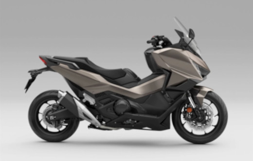
The Honda Forza 750 is Honda’s flagship sport GT scooter featuring a 745 cc parallel-twin engine, Dual Clutch Transmission (DCT), electronic ride modes and cruise control. This page contains one of the most comprehensive Honda Forza 750 technical specification databases available online, including official specifications, workshop data, maintenance information, dimensions, suspension settings, engine specifications and electrical data.